Annular Volume - Data Entry | Pipes (Oilfield)
The "Annular Volume" module allows the quick computation of the annular volume between:
- Two strings of pipe
- A string of pipe and the open hole
- A string of pipe and a combination of pipe and open hole.
- Casing and Liner Cementing Jobs
- Cement Plug Jobs
- CT Cement Plug Jobs
- Bottom-Up Volumes
- Annular volume between Pipe/Hole and a CT string as well as CT capacity taking in consideration a CT reel volume at surface.
The outer sections can all be open hole, pipes or a mix of both.
The depths against each section represent the depth of the bottom of this section and NOT the length of the section.
The pipe sections can be of different type (casing, DP, Tubing or Coiled Tubing), sizes (OD and ID), wall thickness and weight.
The Pipes (Oilfield) App includes a database of all API casings, drill pipes and tubings. It also includes the most common coiled tubing and open hole sizes.
In the "Annular Volume" module, two strings need to be defined:
- The Outer String and
- The Inner String
The below steps shall be followed to add the desired pipe/OH to the corresponding section of the outer pipe/OH string :
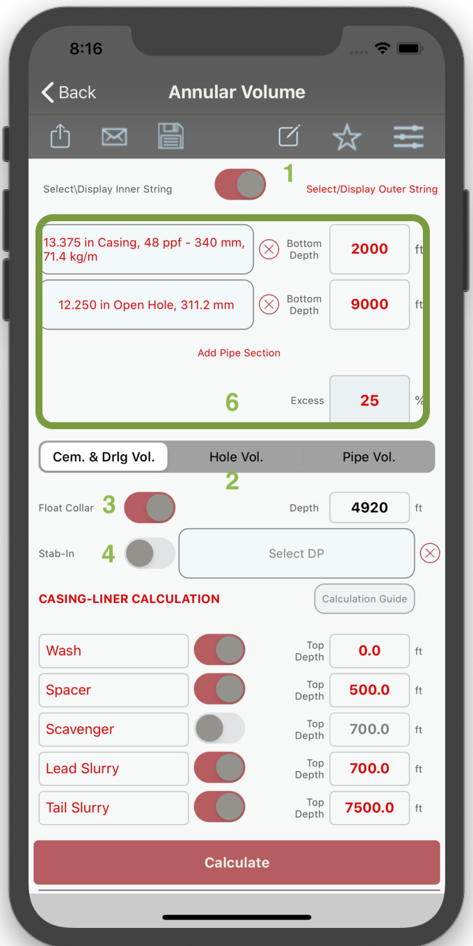
- Set switch (1) to ON to allow saving pipe/OH data to outer string (The color of the buttons in the input section (6) will change to red (if in light mode) or light blue (if in dark mode) to confirm that entry is being made to outer string)
- Press the desired pipe/OH string in the input section (6)
- Follow the “Select Section” instructions.
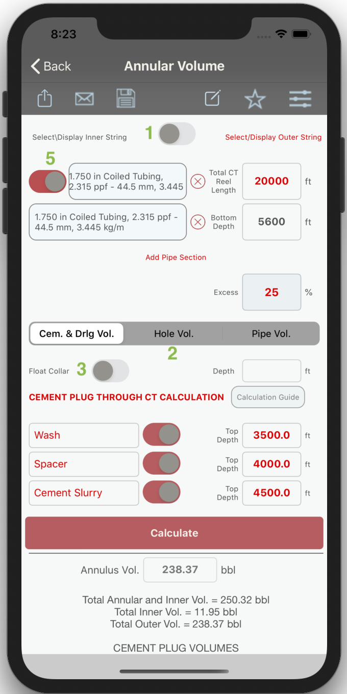
- Set switch (1) to OFF to allow saving pipe data to inner string (The color of the buttons in the input section (6) will change to black (if in light mode) or white (if in dark mode) to confirm that entry is being made to inner string)
- Press the desired pipe/OH string in the input section (6)
- Follow the “Select Section” instructions.
Notes :
- The bottom depth of the inner string must be equal or less then the bottom depth of the outer string.
- It is optional to enter all three pipe/OH sections in the strings so, you can enter only one or two pipe sections.
- If user elected to enter only one or two pipe sections, he needs to input the corresponding end-of-pipe depth of these pipe sections only. The calculator will consider the depth of the none used sections similar to the depth of the last entered section (Top or Middle section).
Primary Casing & Liner Cementing
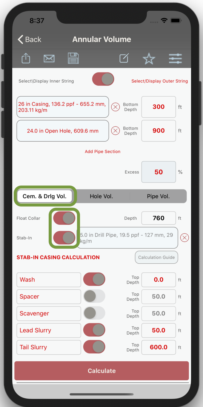
Stab In Primary Cementing
The segment control (2) and the switches (3), (4) and (5) are then used to switch between the different calculation modes.
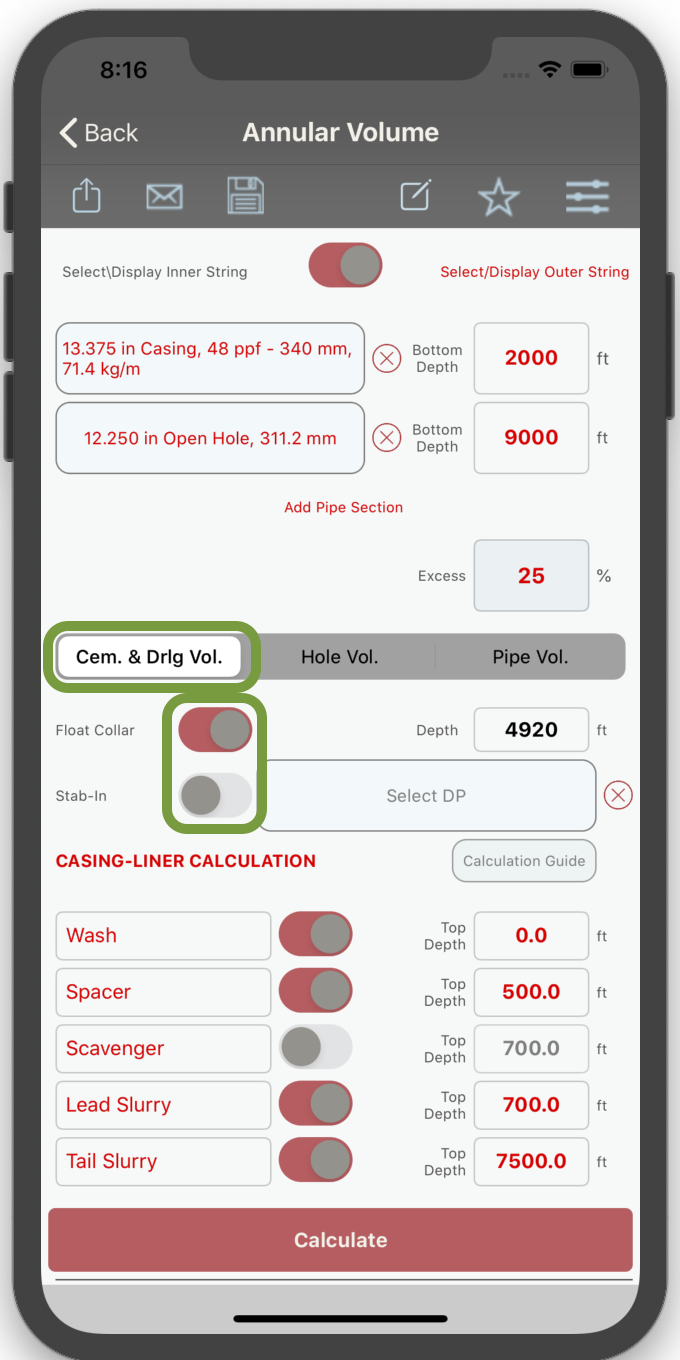
When “Cement & Drilling Volumes” is selected in the segment control (2) and :
- the collar and stab-in switches are set to ON, the module will compute the volumes for a stab-in cementing job and the stab-in string selection will be enabled
- the collar switch is ON and the stab-in switch is OFF, the module will compute the volumes for a primary cementing or a liner job. Also in such case, the stab-in string selection will be disabled.
- the collar switch is turned OFF, and all fluid switches are turned OFF, the module will compute the Bottom-Up volume. If a Rat-Hole is present, the volume of it will be displayed in the output section.
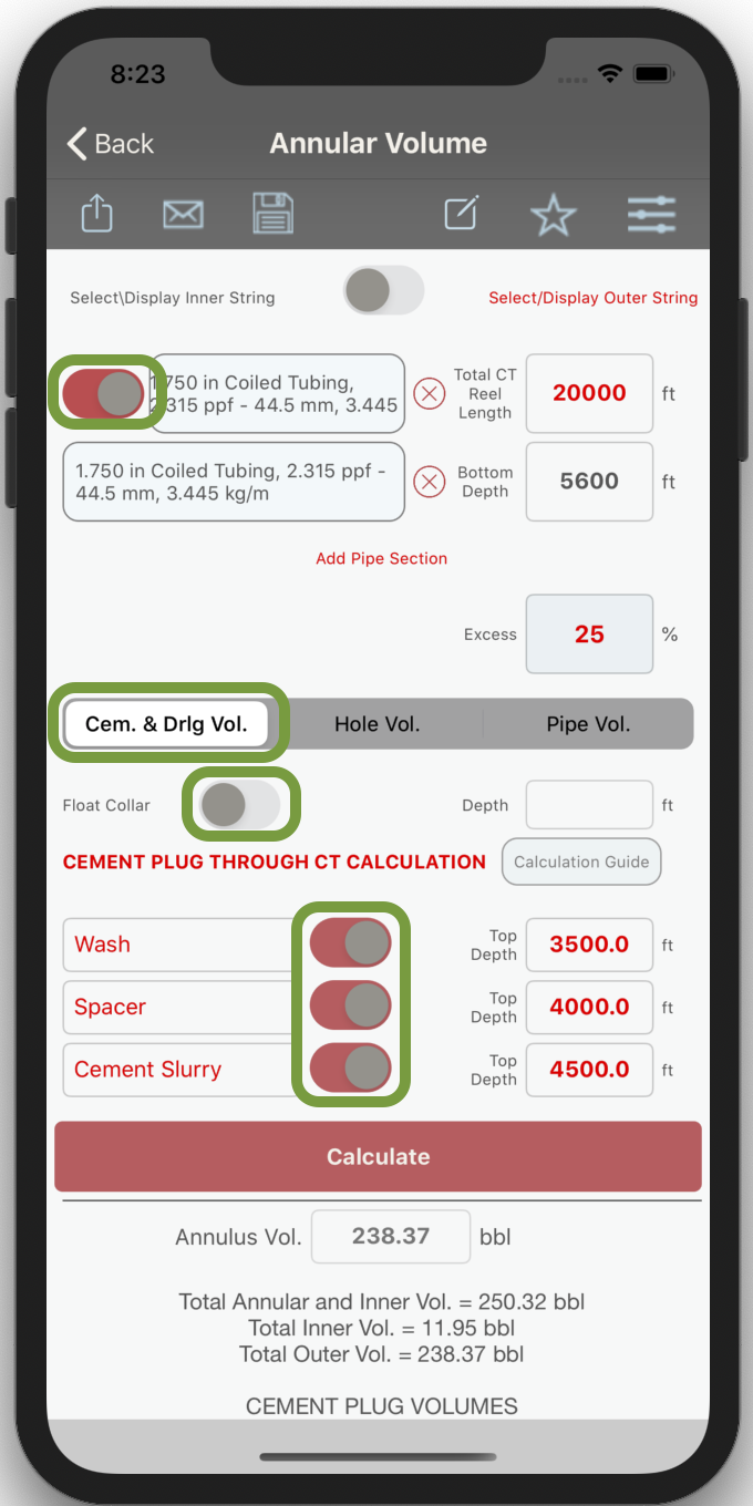
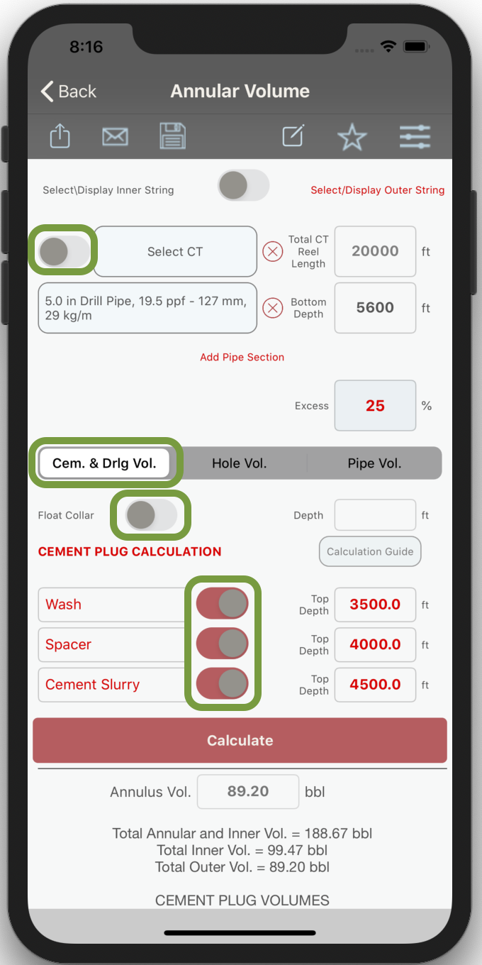
- the collar switch is turned OFF, and any fluid switch is turned ON, the module will compute the volumes for a cement plug job. Only three fluids are available when computing cement plug volumes, these fluids are; wash, spacer and cement. Also in such case, the coiled tubing option will be available to calculate the volumes for a cement plug through coiled tubing job:
- if the CT switch is ON, the option to input a CT reel and the length of the reel will be accessible and a calculation of a cement plug through CT will be run. The placement of cement plug thru CT assumes that:
- the coiled tubing will be POOH once the cement exits the end of the CT
- the end of the pipe will be just below the required top of cement at the end of cement pumping.
- the top of cement provided in the data entry is considered the top of cement without pipe and so is the volume volume of cement computed.
- the displacement volume is equal to the CT reel capacity.
- if the end of the coiled tubing is placed off-bottom, the rat-hole volume below the CT down to the bottom of the hole will be displayed in the output section
- if the CT switch is OFF, the option to input a CT reel and the length of the reel will not be accessible and the calculation of a balanced plug through DP will be run. The placement of cement plug assumes that:
- the top of the cement provided is the required top of cement without pipe in the hole.
- the displacement volume is calculated to balance the plug while the pipe is immersed in the fluids.
- if the drill pipes’ end is placed off-bottom, the rat-hole volume below the DP down to the bottom of the hole will be displayed in the output section.
An open hole excess can be used in the computation of the open hole volume (the excess can also be applied to the pipe sections if this option is selected in the settings screen) else it will be only applied to the OH volumes. The excess percent can be then entered in the textfield in the input section (6).
When “Hole Volume” is selected in the segment control (2), only the outer string will be available for data entry and the volumes of the open hole and previous casings will be then computed.
The volume of up to five different fluids can be entered and computed. The name of each fluid can be entered by the user in the corresponding textfield. This name will be used when exporting the data via email or shared.
Note: the main difference between “Outer Volume” calculation and “Inner Volume” calculation is that in “Outer Volume” calculation the user can input a combination of pipe and open hole sections wine in the “Inner Volume” calculation only a combination of various pipe can be input.
An open hole excess can be used in the computation of the open hole volume (the excess can also be applied to the pipe sections if this option is selected in the settings screen) else it will be only applied to the OH volumes. The excess percent can be then entered in the textfield in the input section (6).
When “Pipe Volume” is selected in the segment control (2), only the inner string will be available for data entry and the inner capacity of the string will be then computed. No excess can be applied to the inner volumes.
Also, the volume of up to five fluids inside the inner pipe can be computed. The name of each fluid can be entered by the user in the corresponding textfield. This name will be used when exporting the data via email or shared.
- If the collar switch is set to ON, the module will compute the inner pipe capacity down to the collar depth only. This calculation can also be useful when computing the volumes down to a specific depth or down to a restriction in the pipes. In such case the point of concern shall be entered as the collar depth.
- If the collar switch is set to OFF, the module will compute the inner pipe capacity down to the bottom of the pipe string.
Cement Plug
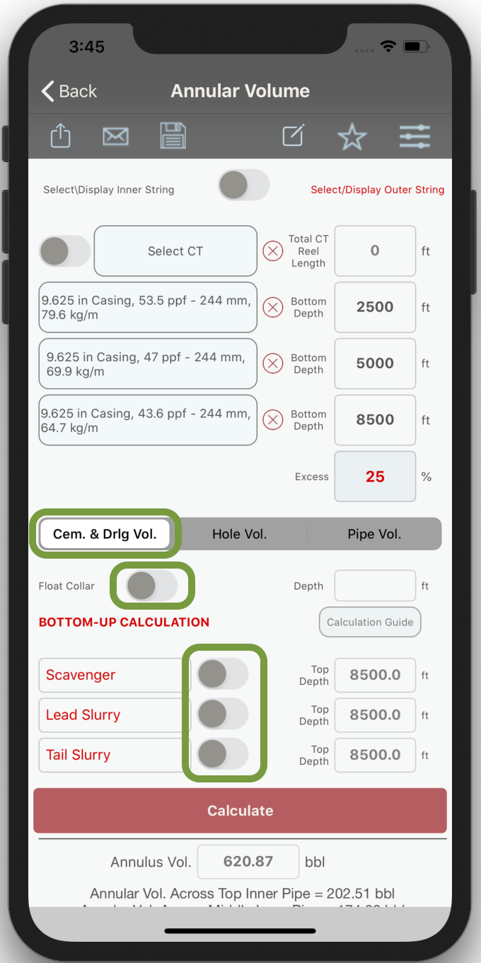
Bottom-Up Calculation